The Buss-E '71

Early Bay Forum

Help Support Early Bay Forum:

This site may earn a commission from merchant affiliate links, including eBay, Amazon, and others.
gvee said:
Good work on the electrics!

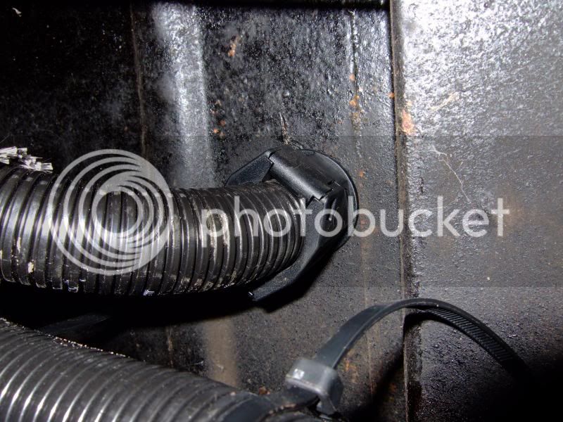
Question for you: where do you get this grommet/clip thing (and what's it called for me to find)?

DSCF8364.jpg

Hey George,

try this link:

http://www.polevolt.co.uk/acatalog/Through_Panel_Adaptors__Elbows___Breakout_Adaptors.html" onclick="window.open(this.href);return false;

The one in the picture is a big one (CTA163) for a 22mm internal conduit. Be careful, I got carried away on this site and spent a small fortune. Makes and protects any wiring like factory so actually quite a small price to pay given what we all spend on these old buses.

cheers

Paul
 
Wow! It's been nearly 10 months since i posted last. I haven't stood still on the bus but as always it's been slow.
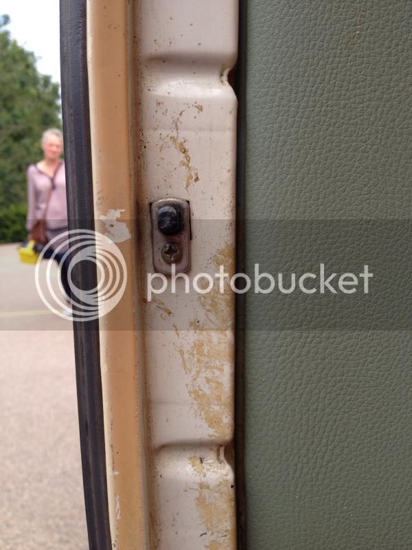
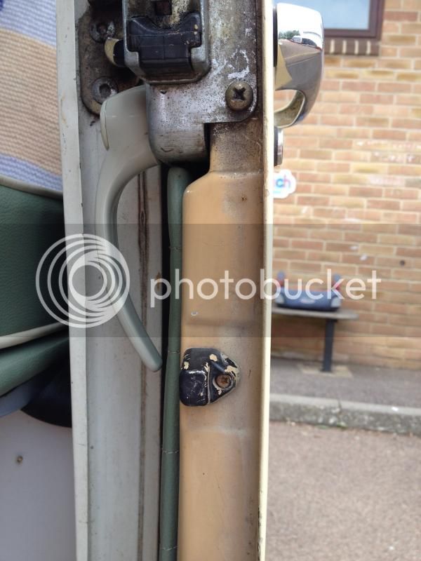
A few pages back I asked if anyone had an idea where the positioning of the sliding door courtesy light switch should be placed. Well, I attended a small car show at my daughters school and someone turned up with a a Bay with it fitted as standard so here are the pics if anyone is interested.

B Post


Sliding Door

 
Buss69 said:
Wow! It's been nearly 10 months since i posted last.

Not good enough :poke:

Buss69 said:
A few pages back I asked if anyone had an idea where the positioning of the sliding door courtesy light switch should be placed.

I still have not installed those parts for my door yet, so I couldn't help, but that picture will help me :party0021:
 
cunning plan said:
Buss69 said:
Wow! It's been nearly 10 months since i posted last.

Not good enough :poke:

Buss69 said:
A few pages back I asked if anyone had an idea where the positioning of the sliding door courtesy light switch should be placed.

I still have not installed those parts for my door yet, so I couldn't help, but that picture will help me :party0021:

Not Good enough! It's a goddam travesty, I bow my head in shame. Like yourself been so busy at work, I've had to learn some new tech stuff and it's left me brain dead! I'm going to attempt to make up for it now though. Read on.
 
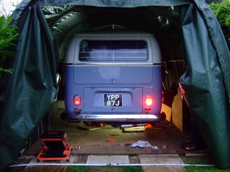
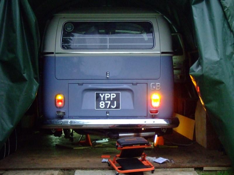
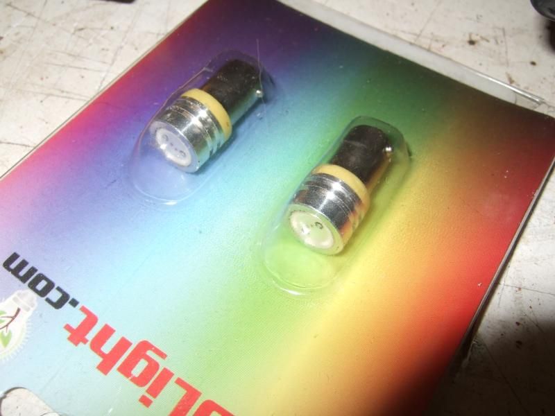
Next I fitted LED stop/tail and indicator lights in the bus. I bought them from a well known VW parts supplier and have to say I thought they looked a bit dim. So I did a comparative test against a normal incandescent bulb that we all normally fit. This is the result. The new LEDs lamps are fitted on the left.

Tail Lights only


Indicators with tail lights


As can be seen the LED's are next to useless and probably not all that safe. One of the major factors here is that the LED's don't really illuminate the reflector of the bulb holder in the same way a normal bulb does. They have LED's that shine on the reflector but they are simply not man enough for the job. Now the parts supplier does have a sticker on all the packaging that says not for road use but I kind of have to ask, why bother selling sub standard parts they really are a waste of money, and there're not cheap either.

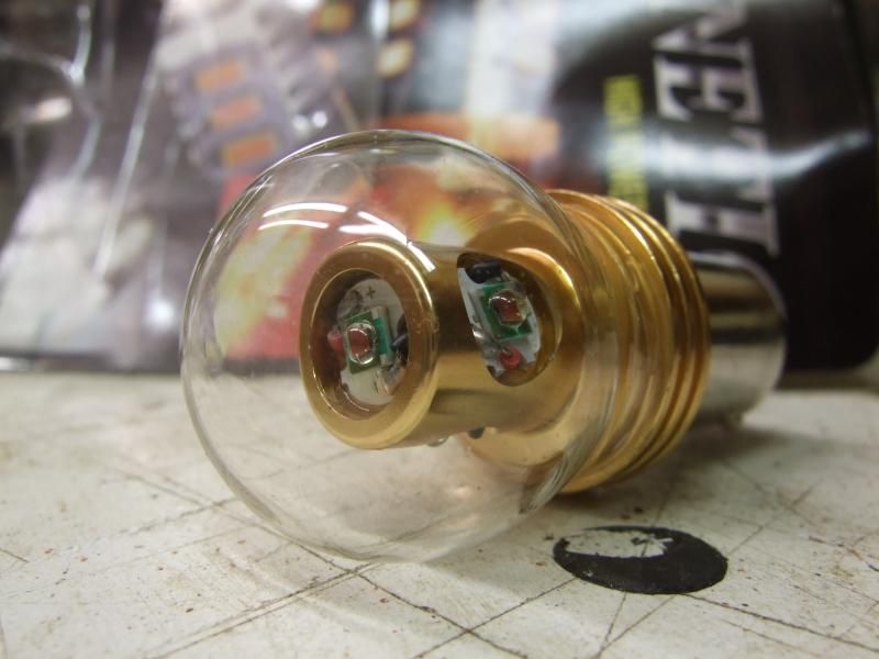
Because of this I did a bit of digging and found Cree LED bulbs on the net. For some reason and maybe we could all be enlightened here the US parts suppliers will not supply to the UK, not sure why so I asked a relative visiting from the US if they could bring some over. Small ones for Side Repeaters


and... these ones are indicators


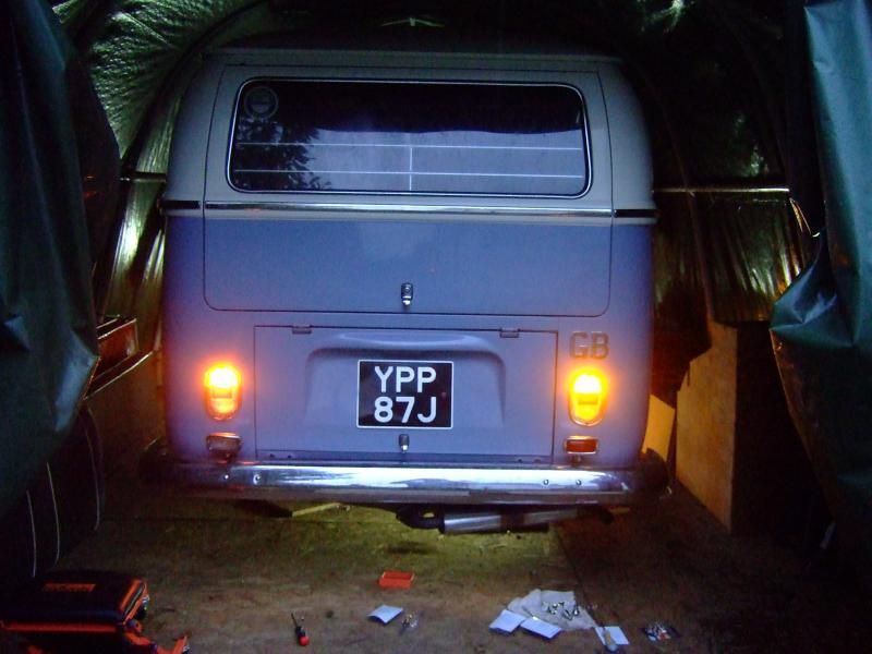
I fitted Cree's for the Stop/ Tail as well. These are all Cree's except for the right hand Tail light which is a Plasma (posh LED)


Have to say I'm pretty happy with the results the finish of the Cree's is better than the Plasmas but both are excellent in terms of light output and are very similar if not the same as normal incandescents which is what I was after.
 
Also I posted a separate thread on the site with the following but thought it wise to spread the word as it regards safety and a potentially disastrous scenario. One of the many reasons I upgraded/ renewed my wiring.

One night whilst driving my bus to my in-laws with my niece and nephew on board I took a route down dark country lanes of Oxfordshire. I had my headlights on and switched to main beam. All good for about 10 seconds when suddenly all my lights went out except the side lights which where next to useless.
A 5p, 50p moment occurred :shock: , it was very scary.
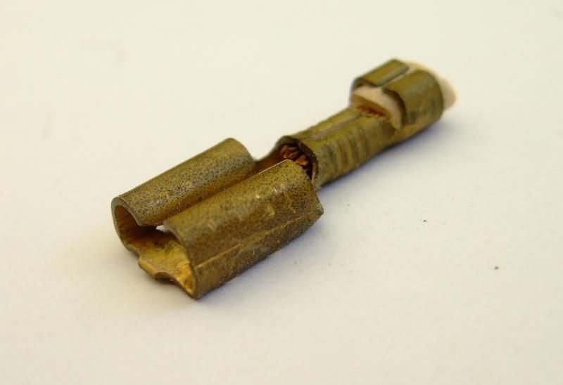
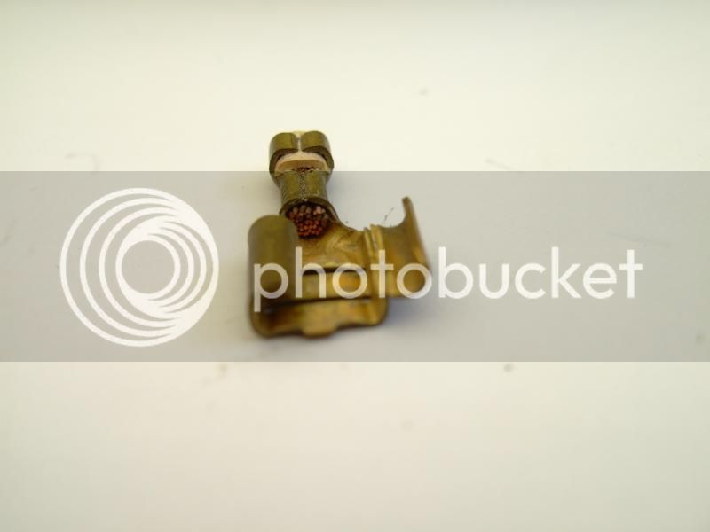
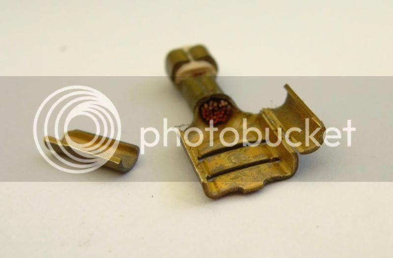
Luckily I knew the road, flicked the hazards on and coasted round the corner before working out that something was up with main beam. When I took the loom out I inspected the OG fuse box and this is what I found.


Doesn't look too bad until you look closely and see the hairline crack in the connector. It's enough to make sure the power stops getting to the headlights.

Please everyone check yours. I wish I had or at the least knew what to look for, I went through numerous relays and three sets of indicator stalks before I worked out what is was. I dread to think what would have happened if had not been on familiar roads.

It took very little to do this


and not a great deal to do this either

 
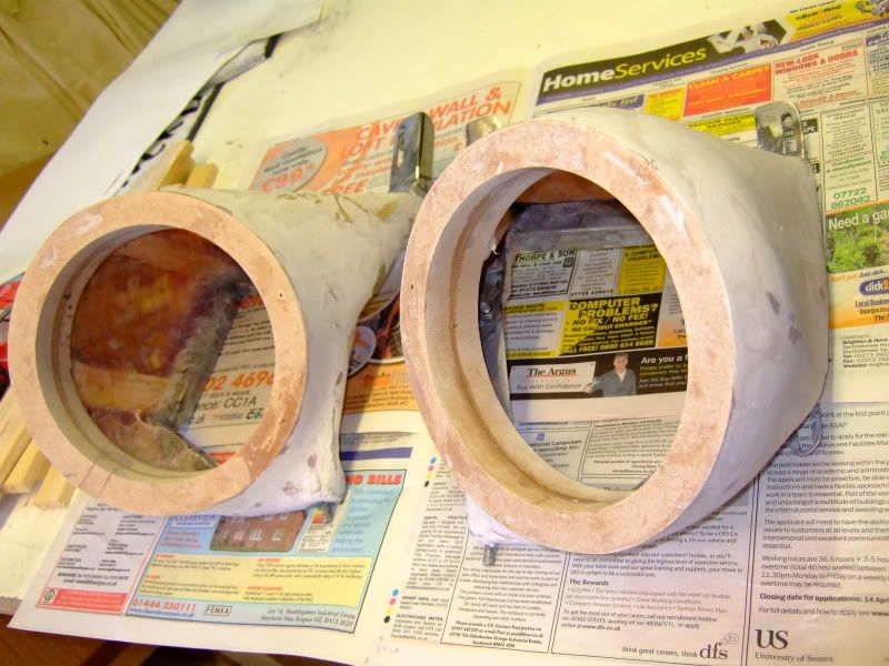
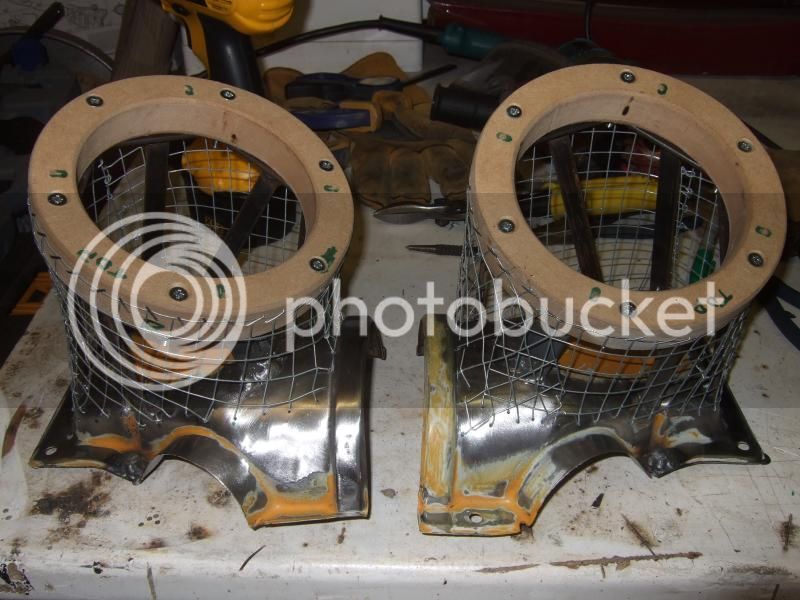
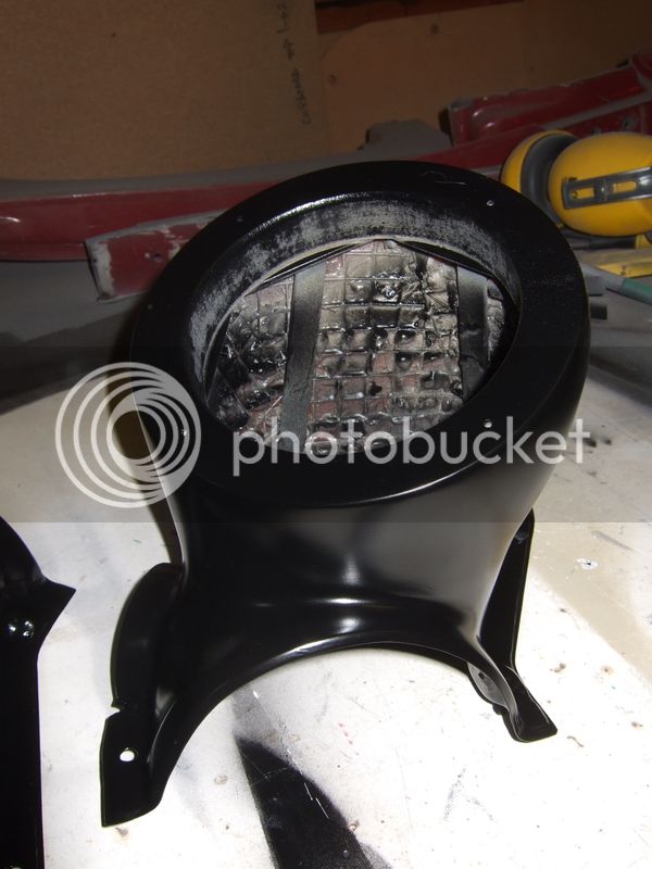
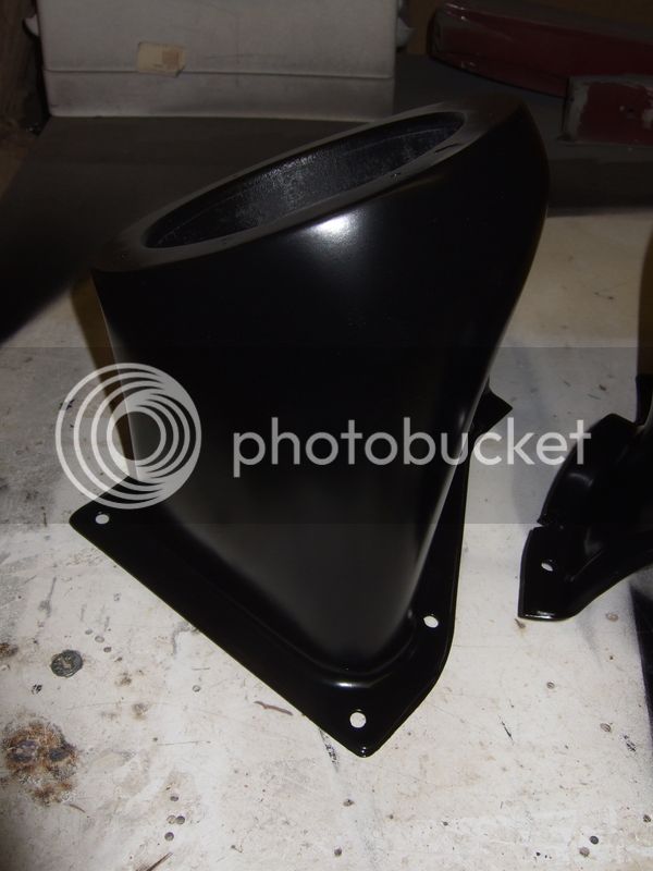
Right next instalment is involving the Speaker pods I was making for the front kick panels. I got this far


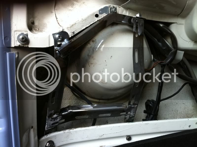
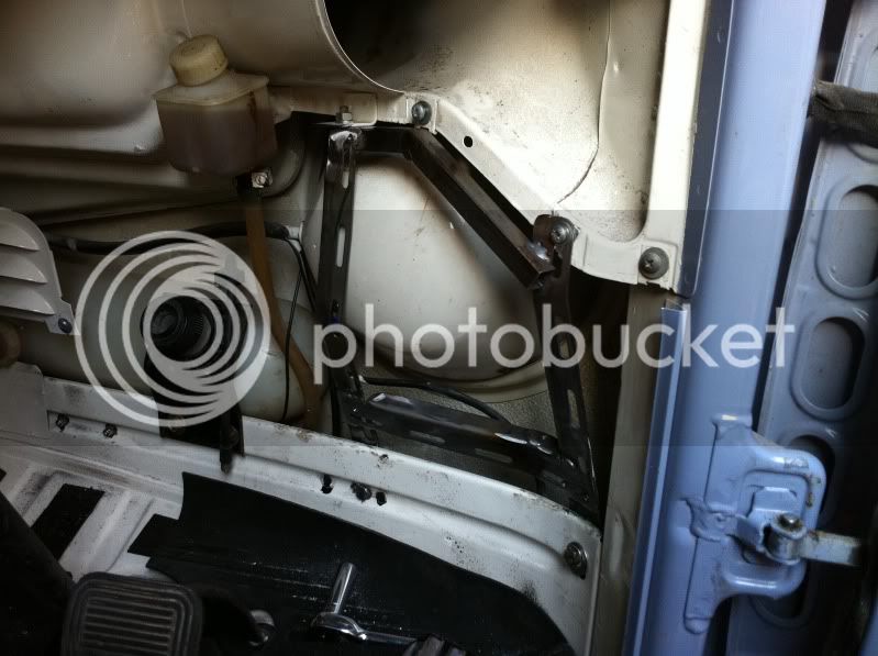
And this is where they were supposed to fit. These are the frames the pods where built onto.


Well I got them fitted up thinking everything would be OK. Well... it wasn't. I trial fitted the pods and came to the conclusion that the one on the drivers side interfered with my right foot too much. It wasn't terrible but felt that in an emergency could I miss the brake pedal? Not sure actually but wasn't prepared to risk it to be honest so went back to the drawing board.

One thing I've tried to do with all the mods on my bus is to make them easily reversible so things could go back to stock easily (I know it looks complicated but the loom is exactly the same as the OG but with additional wiring, still using VW colour conventions and use). So with this (loose) mantra in mind I'm trying a test run on our '03 Brazilian. If it works well I'm going try something similar in the '71.

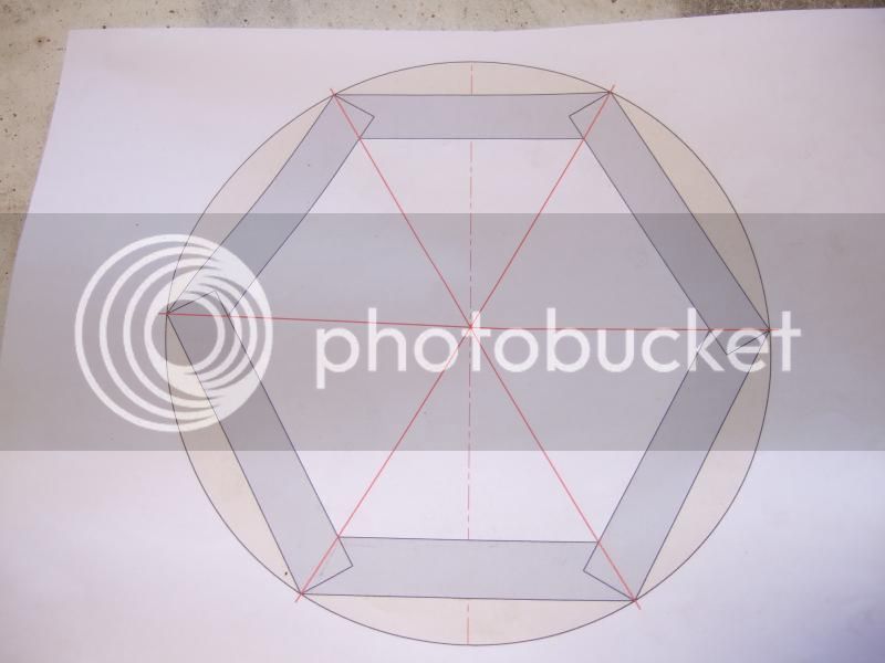
1:1 drawing first


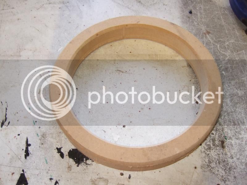
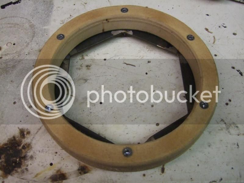
Then made a set of mounting rings


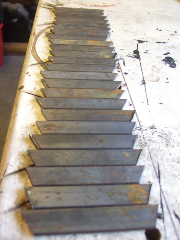
Cut the parts for a frame to be mounted to back of the rings


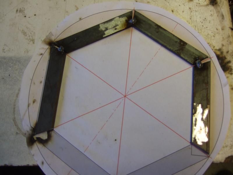
Tacked them together


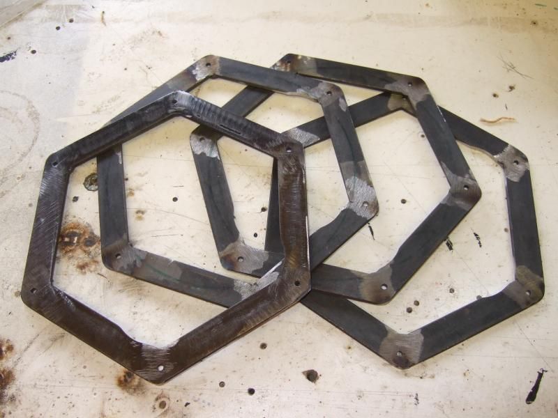
Welded them all up


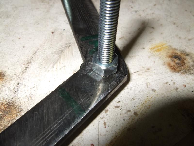
Positioned some nuts to be welded on


and mounted the frames to the rings with countersunk machine screws

 
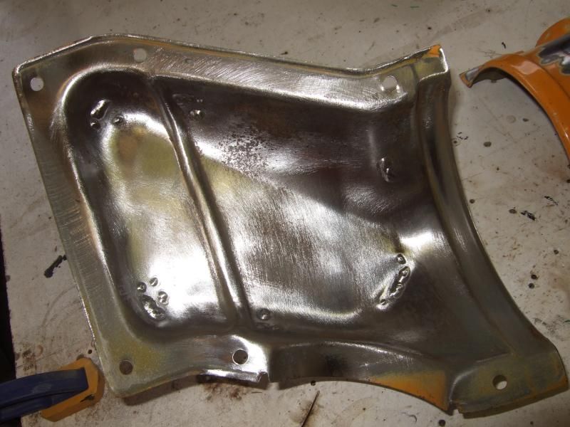
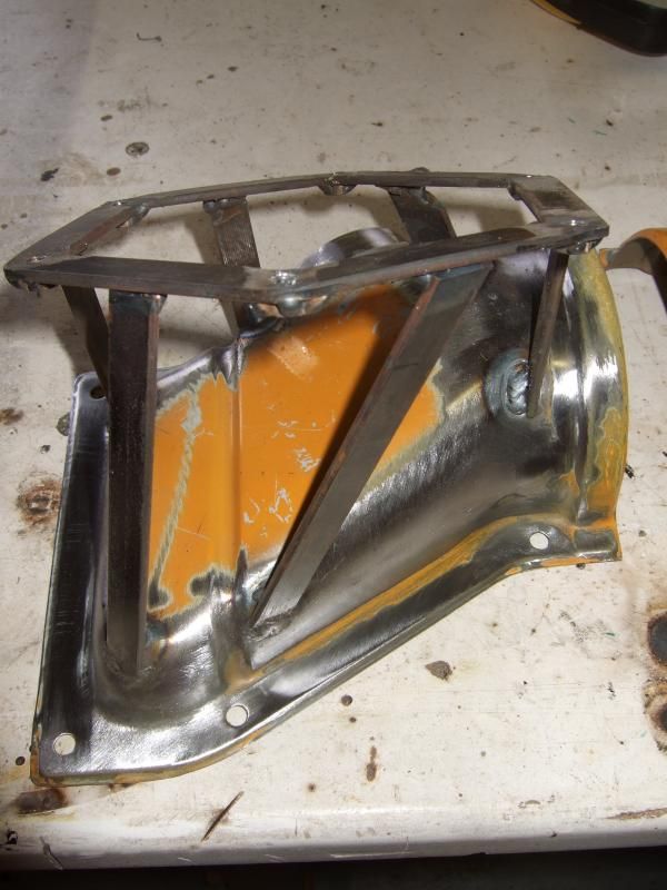
Now my secret mounting position revealed. The heater duct covers, cleaned up.


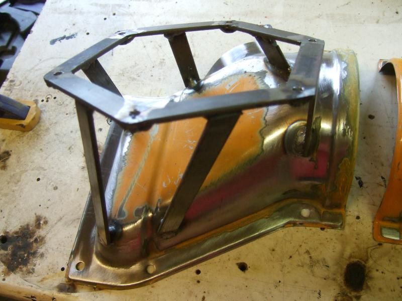
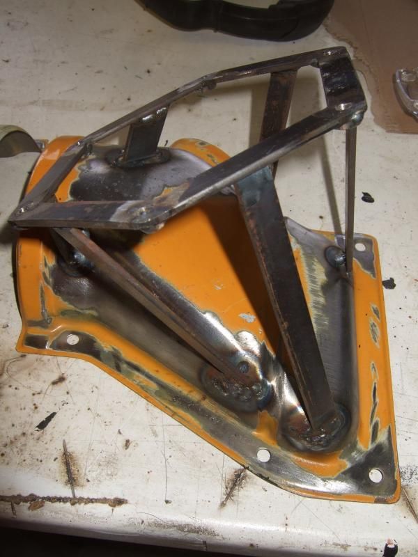
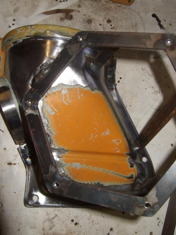
And now for the fun bit. I tacked a piece of bar to the frames and then the heater vent covers. I mounted them in the bus and sat in the drivers seat. Selfishly I angled the mounting rings so they mostly point at the driver. Once I was happy I tacked further bar to the sides for support.


Sorry about my shonky welding, I blew a few holes in the OG steel. Still learning.


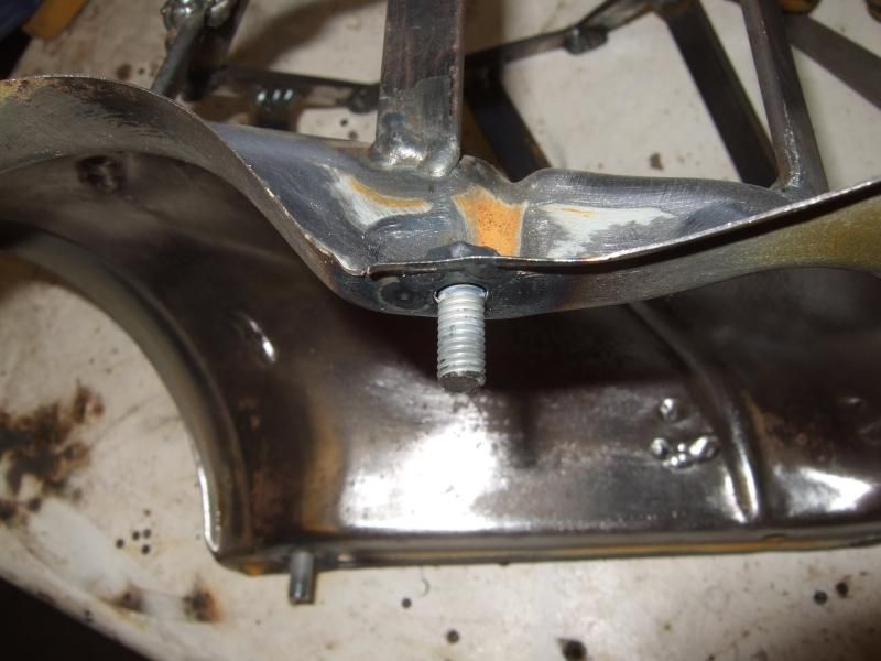
A couple of the mounting holes will end up being inaccessible so I welded captive bolts.


All done and ready for the next stage.


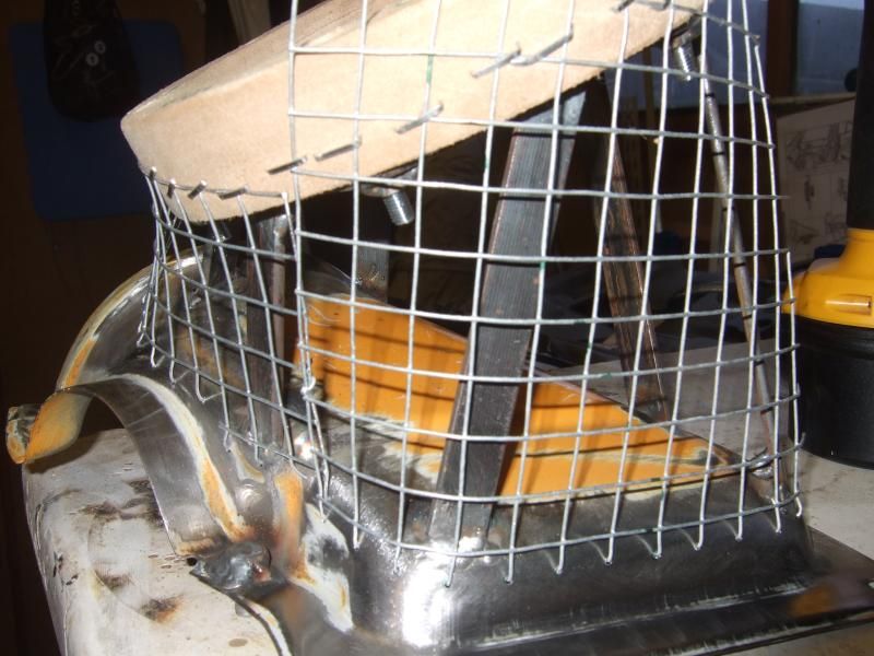
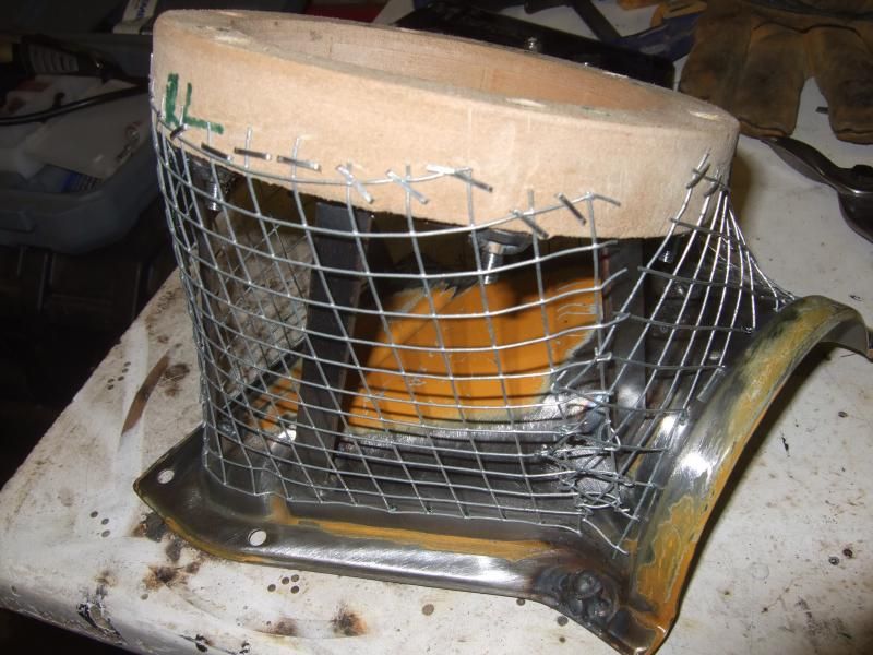
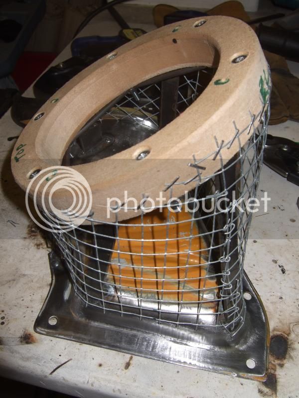
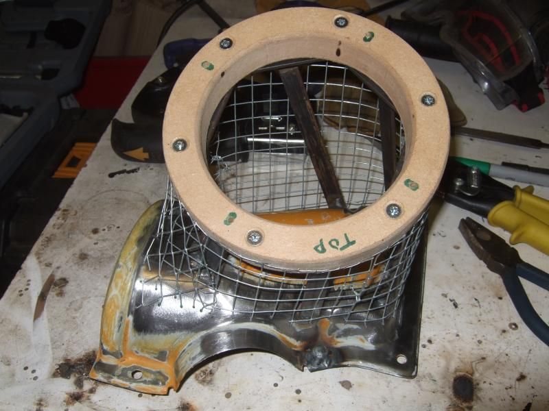
As before I'm using wire mesh to get the basic shape of the pods right, a bit organic.


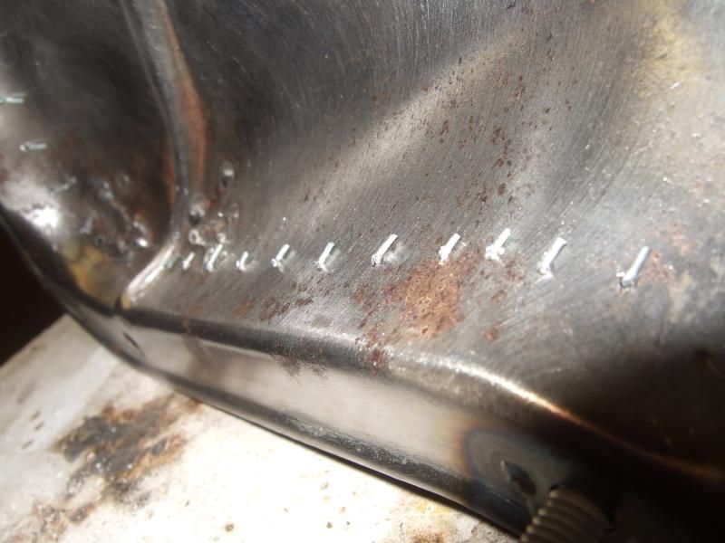
All the mesh is stapled at the top into the MDF rings and at the base I've drilled a series of 1.5mm holes to attach the mesh to the metalwork.


All done and ready for the next stage, hopefully this weekend


As always anybody have any thought on whether this is a good idea or someone has done this before, please let me know. Cheers all.
 
looking good pal.

its nice to see one of us is getting some progress.

however I may be getting back on mine soon if all goes well :D
 
That's some serious intricate work, especially on the speaker pods. And here's me going to just screw them into the kick panels. :lol:
 
andewilson said:
looking good pal.

its nice to see one of us is getting some progress.

however I may be getting back on mine soon if all goes well :D

Hey Buddy, just been looking at your thread. Good luck with the new job position, not sure whether you'll get much spare time if your self-employed. Fingers crossed for you. Did you get your garage built?
 
Supertramp said:
That's some serious intricate work, especially on the speaker pods. And here's me going to just screw them into the kick panels. :lol:

If wasn't an audio anorak I'd do the same. The speakers in the Brazilian where in the door panels, which had rotted, they also sound crap.
 
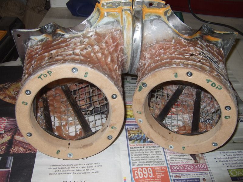
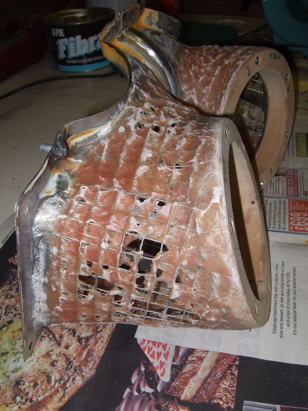
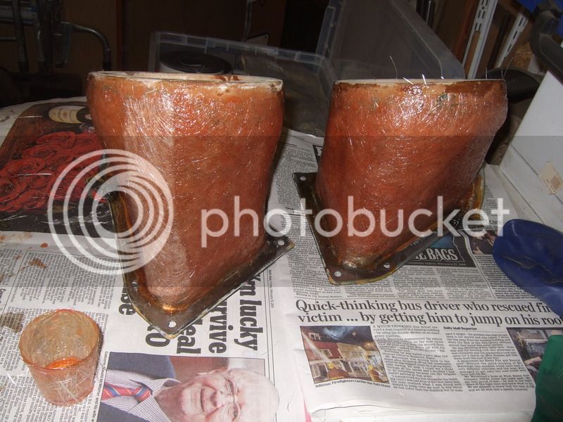
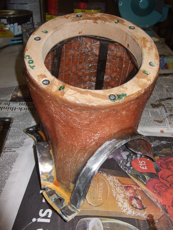
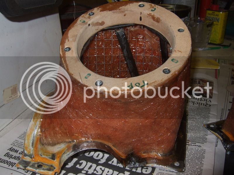
So I carried on with the speaker pods, I'll let the pictures do the talking.
Fibral filling on the mesh and generally all over


I did this so the next layer which will be fibreglass matt has something to adhere to.


My first decent attempt with glass matt. I've tried fibreglass before and it turned out crap. I did a bit more research and when they say only mix a little at a time they mean it. I mixed about 50ml of resin at a time and it worked out well. Very pleased.


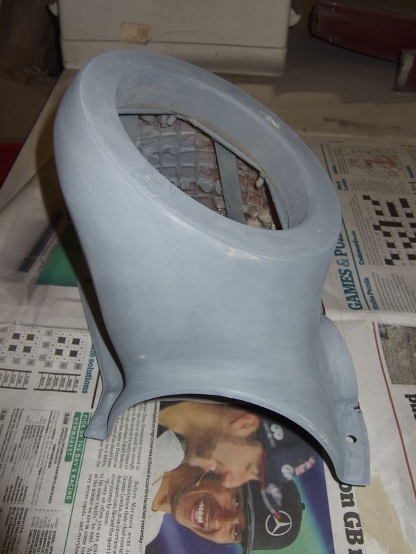
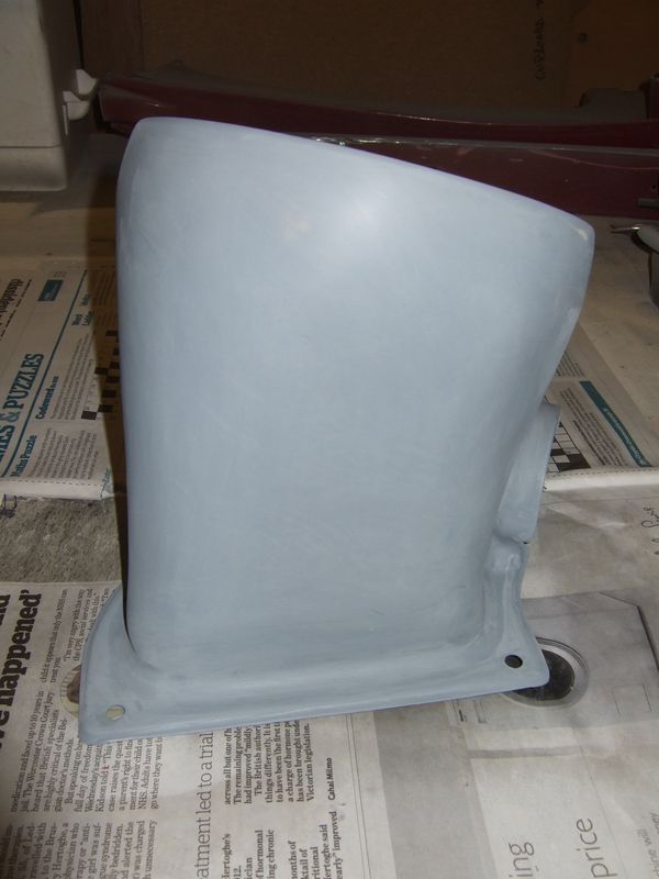
A thin skim of P38 Filler and a lot of rubbing, then primer.


Yet more rubbing down with wet 'n' dry and then top coat

 
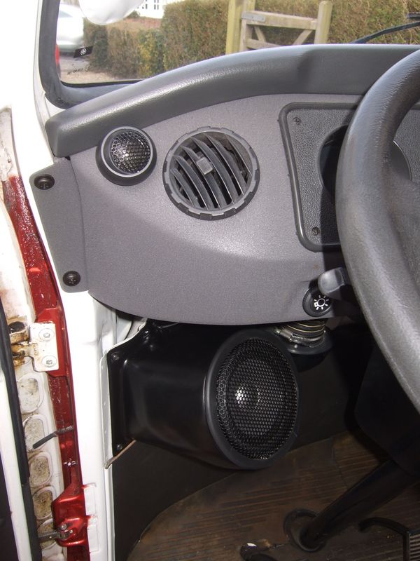
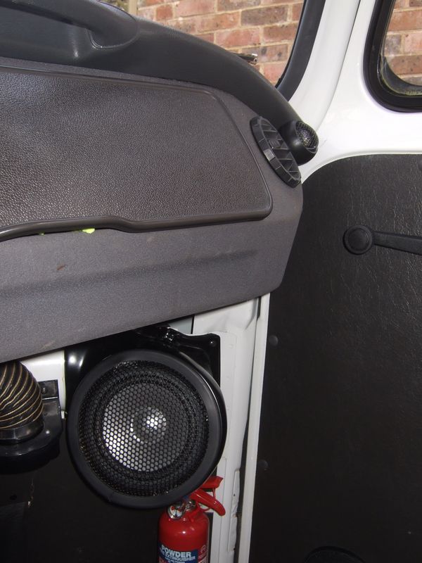
Job done, installed and very happy with the results on all levels. The grills are from Maplins and do a really nice job of finishing it all off nicely. These are component speakers the tweeter is on the dash next to the air vent.


Just about see them all installed


The sound is so much better, mostly because you don't have to crank it up so loudly because everything is pointing at you, happy days.

What I've learn't with this set I'll use in the '71. This time I'll make a better job at blending in with the dash curves and the deluxe air box trim in the door cards. Not sure how it will work out as there will be even less room and the next set of speakers are big and very heavy.
 
Wow a bit of a flurry with progress at the moment, I'm desperate to get this bus back on the road. I can't bare the derision I'm getting from my wife, daughter and mates about how this bus goes no-where. We've actually renamed the '71, "Princess"! She costs a lot, looks amazing and doesn't do anything! (bugger!).

I'm still working on the sound system but need to get this bus back on the ground. The thoughts are, Red 9 Design wishbone set-up for the front with brake up-grade with Porsche stud pattern for a set of chromed Fuchs. For the rear I'm going for a set of Transporter Haus adjustable spring plates with Red9 Rear disc set-up. Does anyone out there have any experience with this set-up on the rear?

Todays work. First off put the Brazilians wheels on the back and loosened of the hub nuts.


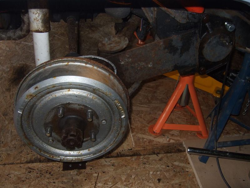
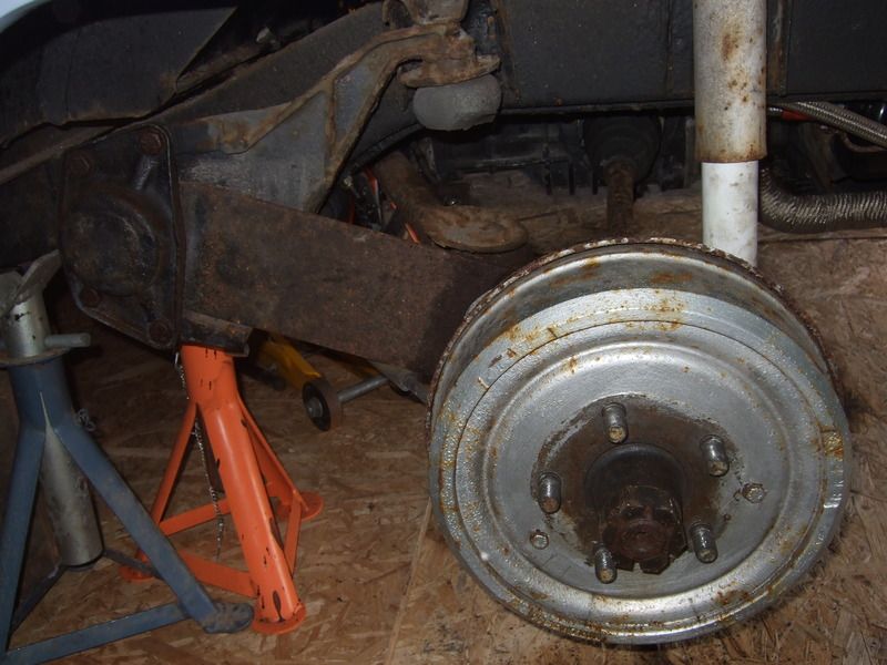
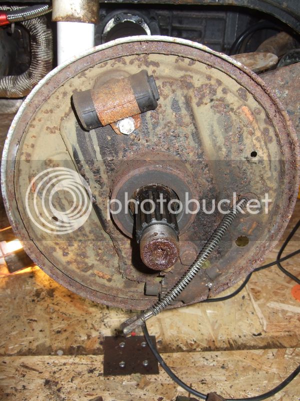
Drums and hubs off.


I know these have a bit of surface rust on them but these brakes have so much life left in them. They've done about 2k.


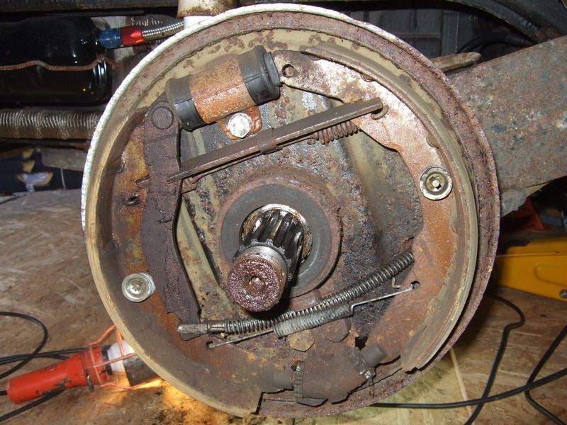
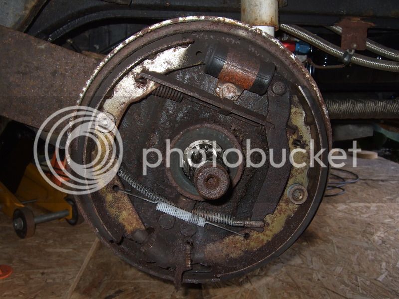
Backing plates off. That was a shit job, the nearside backing plate was really hard to get off. The brakes adjusters on both sides really didn't want to shift. The same with the handbrake cables, got there in the end though. One of the backing plates has suffered though.


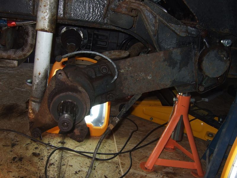
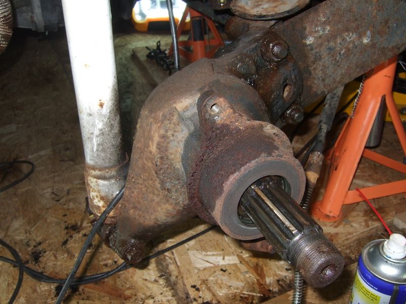
Drive shafts off.


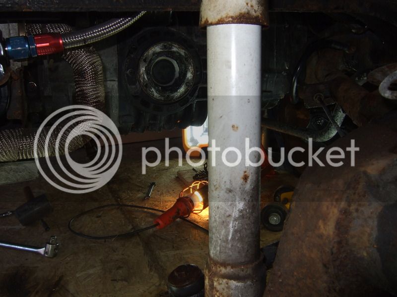
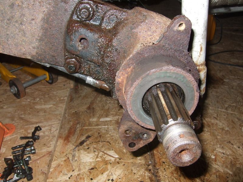
Everything off and ready for the bearing housing removal.


I know I'm not the only person to have done this :lol: but I have a couple of questions. What has everyone else done when removing the bearing housing. The 4 22mm bolts look pretty hardcore i'm sure brut force id going to be the way but are there any tips out there?

What has everyone else done when fitting adjustable spring plates with regard to fine tuning the adjustment of the bearing housing and ensuring it's the same as before removal? Has everyone taken their bus to have the rear wheels aligned and adjusted. it's not something I've read much about? Any advise here guys would be very helpful.
 
* Reserved for reply after the morning's priority work *

EDIT: Right, I can reply with more detail now.

What did I miss, where did the Brazilian bus come from? :? :|

Buss69 said:
For the rear I'm going for a set of Transporter Haus adjustable spring plates with Red9 Rear disc set-up. Does anyone out there have any experience with this set-up on the rear?

Yes, I have experience with the TPH Adjustable Spring-Plates, but not the disc setup. About half-way down this post is where I begin the install if you want to refresh your memory:

http://forum.earlybay.com/viewtopic.php?p=435238#p435238" onclick="window.open(this.href);return false;

Buss69 said:
I know I'm not the only person to have done this :lol: but I have a couple of questions. What has everyone else done when removing the bearing housing. The 4 22mm bolts look pretty hardcore i'm sure brut force id going to be the way but are there any tips out there?

They are actually pretty trouble-free as they are such a nice chunky bolt and thread, they should not be seized and require all the hassle of drilling etc. Just get a good breaker bar and a 1/2" extension, keep it straight on the bolt with one hand and give it a couple of bounces with the other.

Buss69 said:
What has everyone else done when fitting adjustable spring plates with regard to fine tuning the adjustment of the bearing housing and ensuring it's the same as before removal? Has everyone taken their bus to have the rear wheels aligned and adjusted. it's not something I've read much about? Any advise here guys would be very helpful.

The biggest tip I can give you is to measure the end of the current spring plate to a reference point on the chassis. This way, when you put your TPH ARSPs (teehehe arsp...) on, you will know where to set the plate up in its 'highest' position (presuming the bus is currently stock height).

I did not do this, so when I came to put the ARSPs on, I had no idea where stock height was, or even where the old lowered position was. So I had to take measurements from the Bentley manual to set the ARSPs in what I hope is the stock-height position, at their 'highest' setting. However, you get a drop of 1.5" (IIRC) from ARSPs even before you begin to adjust them.

Screen%20Shot%202015-04-20%20at%2009.47.18.png~original


Hope that helps a bit buddy!
 

Latest posts

Top