Gadget Boy
Well-known member
Hi ya Nick
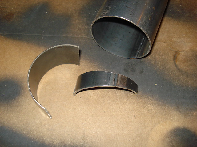
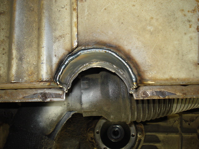
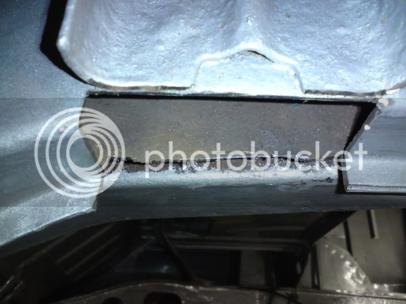
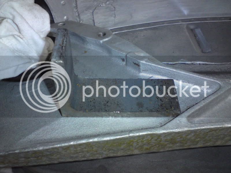
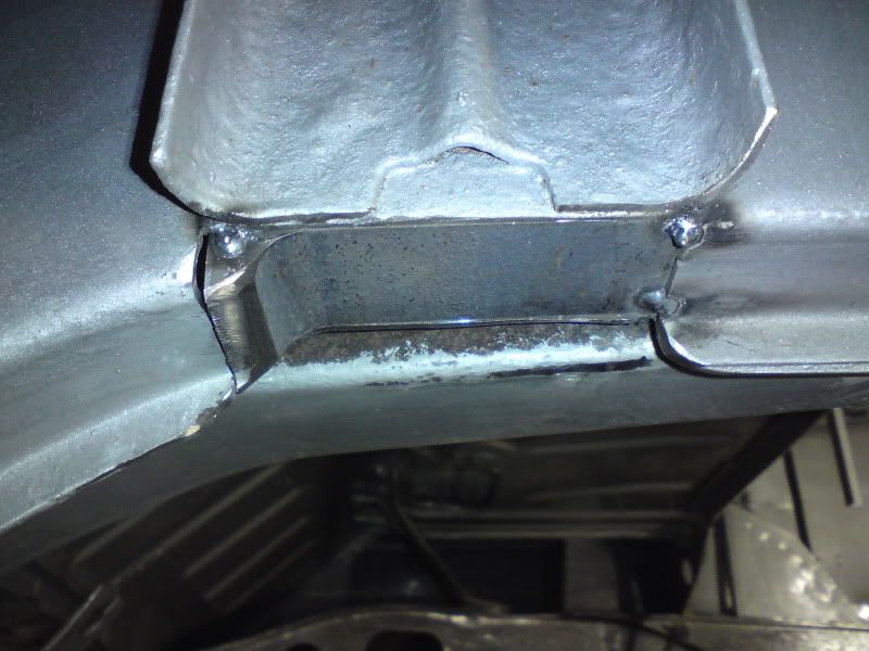
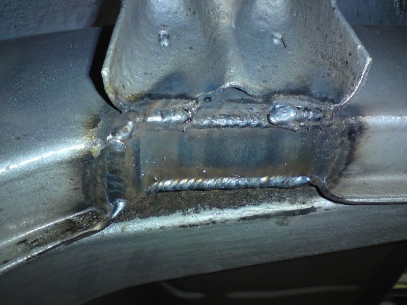
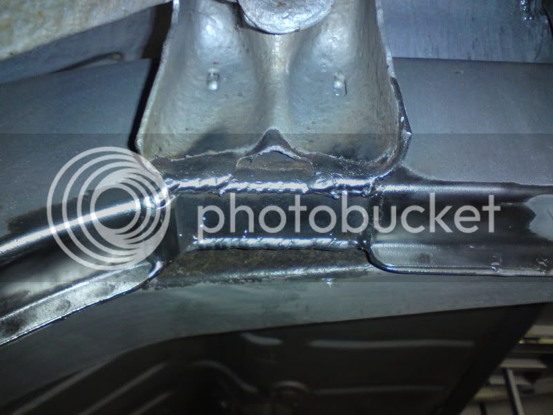
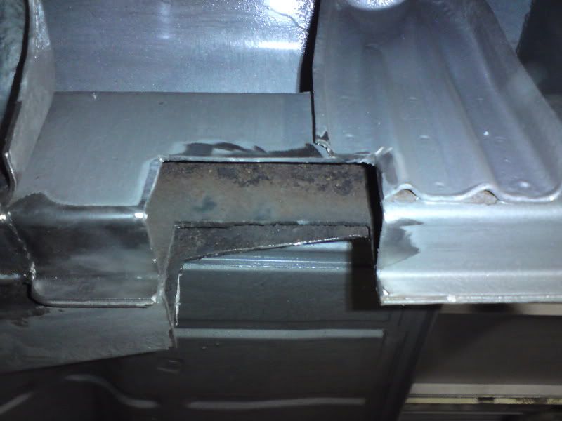
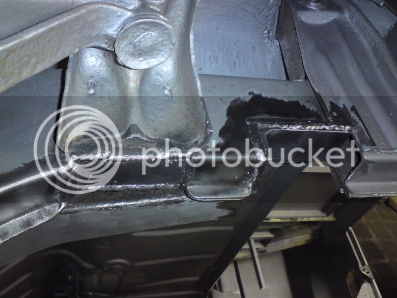
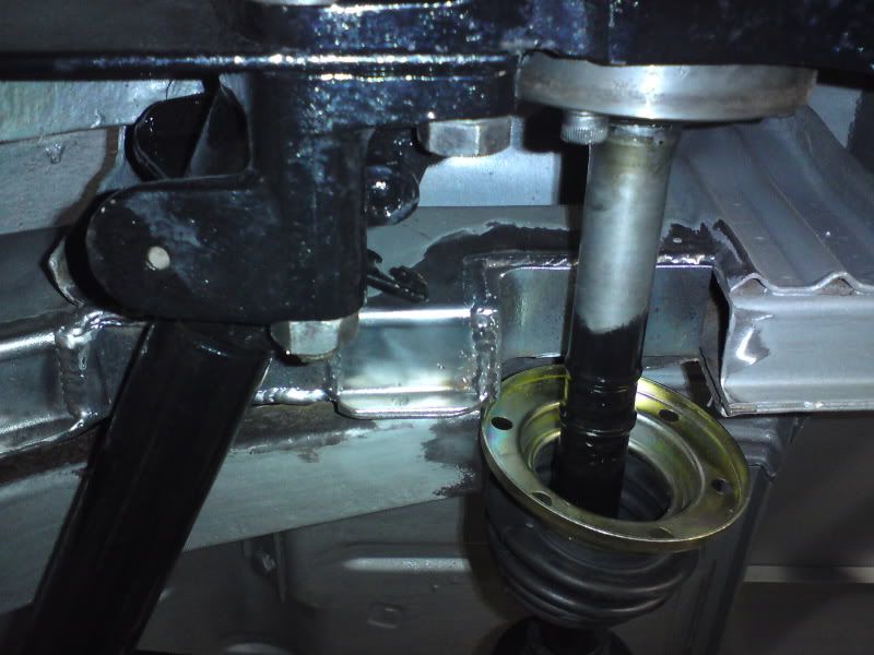
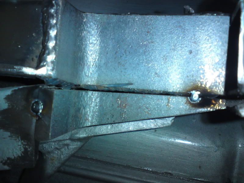
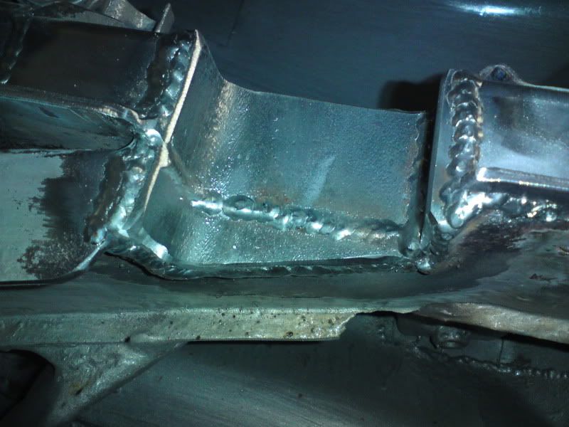
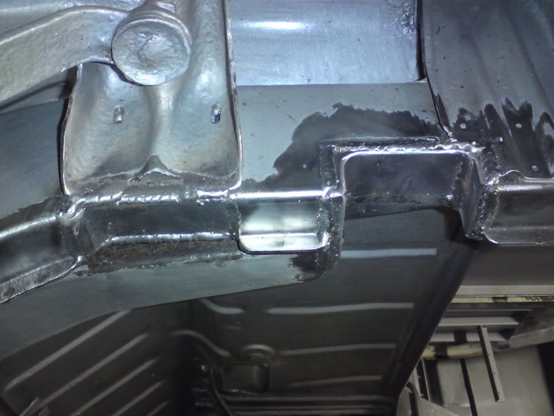
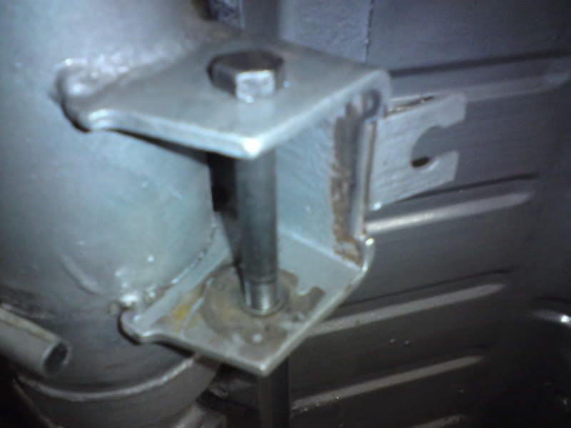
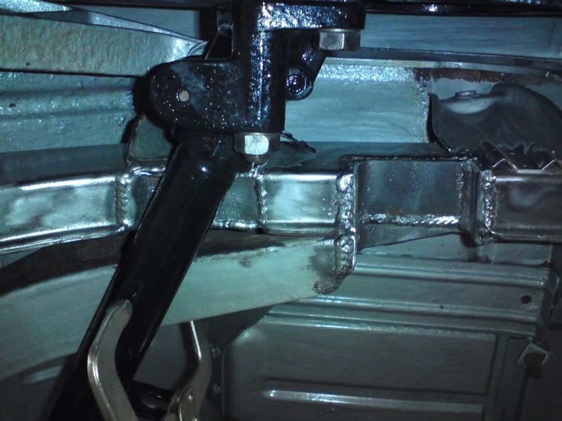
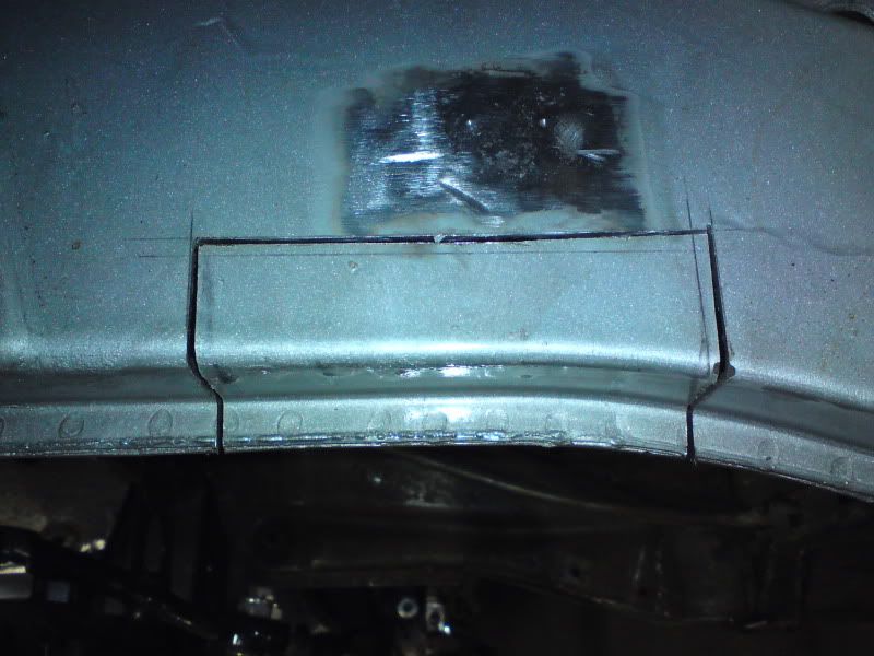
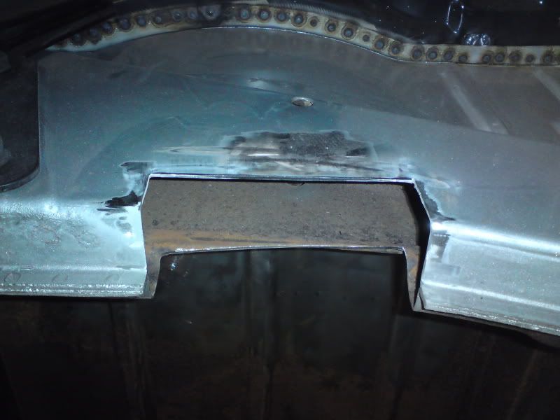
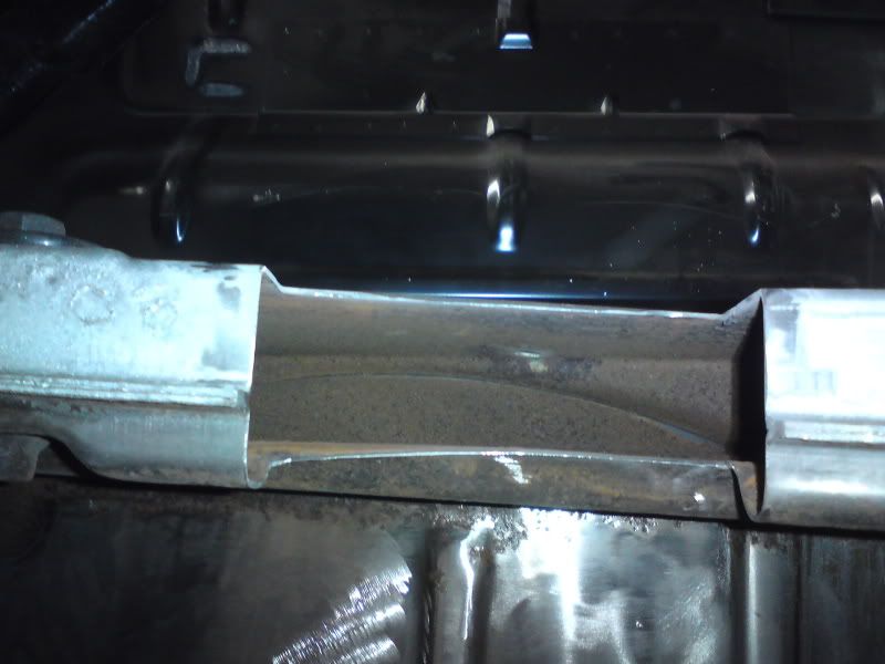
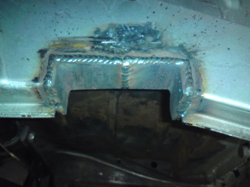
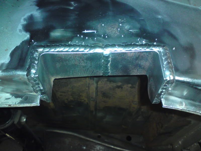
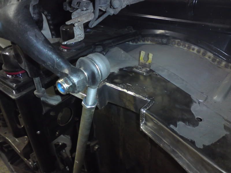
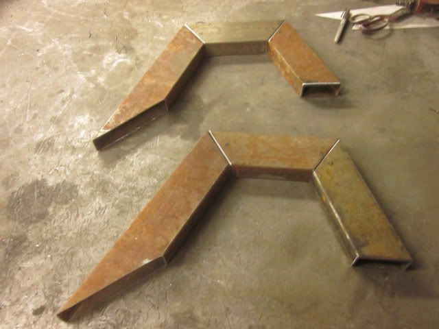
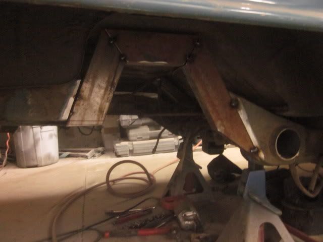
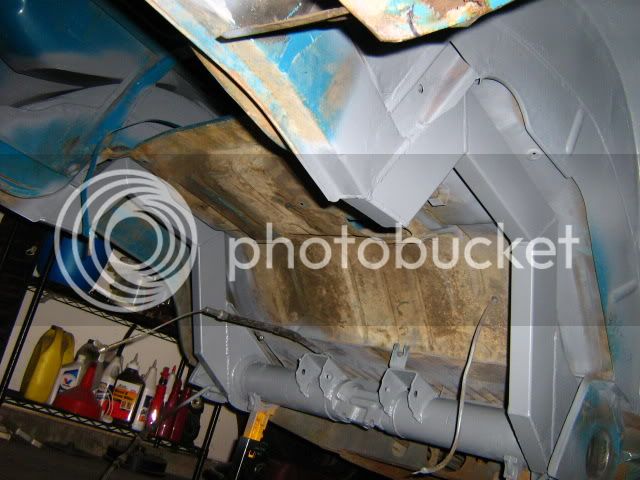
if you look at the photos above , you can see the inner rear chassis braces have been removed, this is due to the depth of the notches into the chassis rails. The inner braces weld to the chassis exactly where the notches need to be , Hence why there removed. On later buses , Im pretty sure its 75/76 onwards the factory deleted them anyway. The box section you can see welded above the chassis rail is 2 x 4 box steel an is the same width as the chassis ( Actually the chassis is 45 mm wide ) But it is stronger than the original chassis ur cutting out and puts back some much needed strength back into the rails. If you look at the picture Evil Ben has posted you can see the infill piece that Ben has welded in for strength from the rear of the torsion housing ( This would usually sit behind the spring plate ) to the chassis rail of the bus .
I cant emphasise enough that if People take the time and effort to research modifications to there buses first , Then we can all build safer stronger buses . It only takes one poorly modified vehicle to be stopped by the police or Vosa and they wont fuck about , they will take it off the road , impound it due to having dangerous modifications done to it , AND we will all end up getting stopped and checked over by them ....
Modify safely kids") 8)
8)
if you look at the photos above , you can see the inner rear chassis braces have been removed, this is due to the depth of the notches into the chassis rails. The inner braces weld to the chassis exactly where the notches need to be , Hence why there removed. On later buses , Im pretty sure its 75/76 onwards the factory deleted them anyway. The box section you can see welded above the chassis rail is 2 x 4 box steel an is the same width as the chassis ( Actually the chassis is 45 mm wide ) But it is stronger than the original chassis ur cutting out and puts back some much needed strength back into the rails. If you look at the picture Evil Ben has posted you can see the infill piece that Ben has welded in for strength from the rear of the torsion housing ( This would usually sit behind the spring plate ) to the chassis rail of the bus .
I cant emphasise enough that if People take the time and effort to research modifications to there buses first , Then we can all build safer stronger buses . It only takes one poorly modified vehicle to be stopped by the police or Vosa and they wont fuck about , they will take it off the road , impound it due to having dangerous modifications done to it , AND we will all end up getting stopped and checked over by them ....
Modify safely kids
8)