Aldon Amethyst Ignition/Custom Ignition Curve Mapping

Early Bay Forum

Help Support Early Bay Forum:

This site may earn a commission from merchant affiliate links, including eBay, Amazon, and others.

rlepecha

Well-known member
Supporting Member
Joined
Jun 11, 2013
Messages
636
Reaction score
4
Location
Leeds
Year of Your Van(s)
1971
Van Type
Microbus
M-codes
095 508 697 A01
Evening all..

Has anyone used a Aldon Amethyst Ignition module before? Its supposed to give you the ability to fully program your mechanical advance and also vacuum advance ignition curves.. Significantly cheaper than an MSD, Mallory or 123tune..

Just thinking about getting one to try and improve performance a bit by creating a custom map for my engine.

Sent from my Siswoo C55 using Tapatalk
 
Hadn't come across it before.
If you do get one, be interesting to know how you get on.
There's a accuspark Blackbox unit for £100, but does have the vac advance.
 
Yeah, I've seen the accuspark one. However I specifically want something that provides some method of measuring engine load, if not then it would be like running a 009!

There's also the CB black box which includes a map/vacuum sensor, this appears to provide a slightly larger advance curve table (21*21 from what I can see). Whereas the amethyst is 16 Rpm related values * 8 vacuum vslues. The areas in between are interpolated by the software. So somewhat reduced adjustment?

Problem is I cant find that CB box for sale in the UK, so box+postage+Import fees would be approx £230 I think!

Sent from my Siswoo C55 using Tapatalk
 
Bit the bullet and ordered one... Will be a good few weeks before I'll get chance to test it all but will provide details and a bit of a guide for others if all goes well!

Sent from my Siswoo C55 using Tapatalk
 
So, created this thread almost 4 months ago and will now update on progress.
Took a bit longer than expected to get my gearbox back, so only got the engine in just after christmas. Done a fair bit of tweaking since using the amethyst module.

I hope this thread will not only provide an insight into the Aldon module, but should also provide some guidance on timing curves using other mappable systems such as the Accuspark Stealth Black Box and 123 Tune distributors. It may also be helpful for those writing custom maps for Megajolt, Megasquirt, Nodiz and CB Performance black box systems, although those systems provide additional timing map flexibility/complexity which I will not be fully detailing in this thread.

I'll start with my engine specs so the thread provides all the detail if anyone looks this up in the future..

Engine:
Stock case
Stock crank
Stock cam
33/30 Dual Port 043 Mexican FI heads, mildly polished ports.
CB performance 1.25 ratio rockers on bolt up shafts
Stock valve springs + pushrods
Twin Weber 34 ICTs, 57 idles + 140 mains, F6 emulsion tubes. 6mm balance pipe between manifolds
CSP bellcrank linkage
CB Performance Maxi 3 oil pump
1/2" Aeroquip hose with An/JIC socketless/push-fit fittings.
Remote filter head + wax stat feeding a Mocal 13 row oil cooler with under chassis scoop.
Facet posi-flo fuel pump & Malpassi filter king set at 3 psi.
Stock heater tubes
Custom stainless steel 4 into 1 exhaust by STG Performance

Ignition:
009 distributor with advance weights removed and plate welded solid.
Compu-fire electronic ignition module
Standard coil, cap & rotor.
Mr.RetroLeads(eBay) performance silicone HT leads
NGK BR6ES spark plugs
Aldon Amethyst mappable ignition module, AM03 model with Vacuum advance MAP sensor.

Gearbox:
CA code 3 rib, with 4.57 ratio ring and pinion. Driving 14" wheels with 195/70 R14 tyres. Not entirely relevant to the ignition module, but added for completeness and I'll upload a spreadsheet later on that calculates RPM at chosen speeds in certain gears etc.

Fuel:
Premium, Shell/BP/Esso 95 ron unleaded, no additional additives.


So, I'll start with the wiring... The instructions supplied with the Aldon Amethyst unit are not entirely clear.
Thick. Black - Earth
Red - Coil +ive or switched ignition (fit inline fuse)
Yellow - Coil -ive
Green - Petronix/Aldon/Powerspark/Compufire etc. black wire.
Thin black - map select or imobiliser wire (not used in my set up)
Petronix/Aldon/Powerspark/Compufire red wire - Coil +ive.

Mounting :

Preferably away from any significant sources of interference, heat and vibration.
I have mounted it in the top left hand corner of my engine bay, on the side of the spare wheel well with countersunk bolts and thick double sided foam for additional support and vibration absorption.

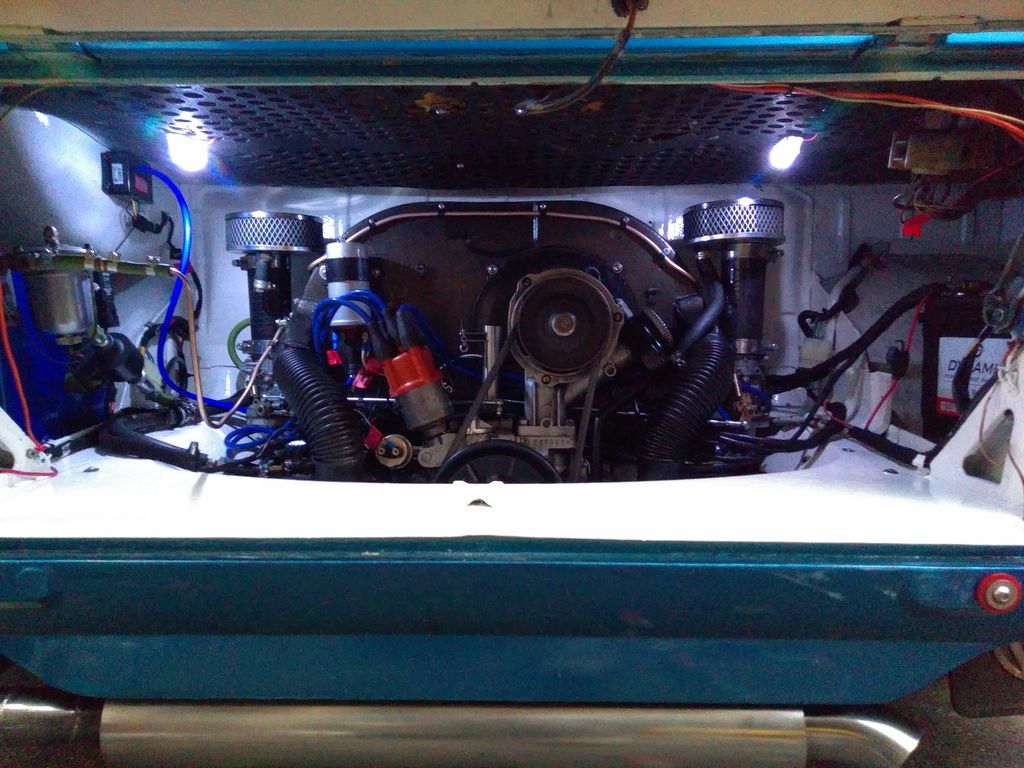
Picture 1 - Engine installed with Aldon Amethyst module.


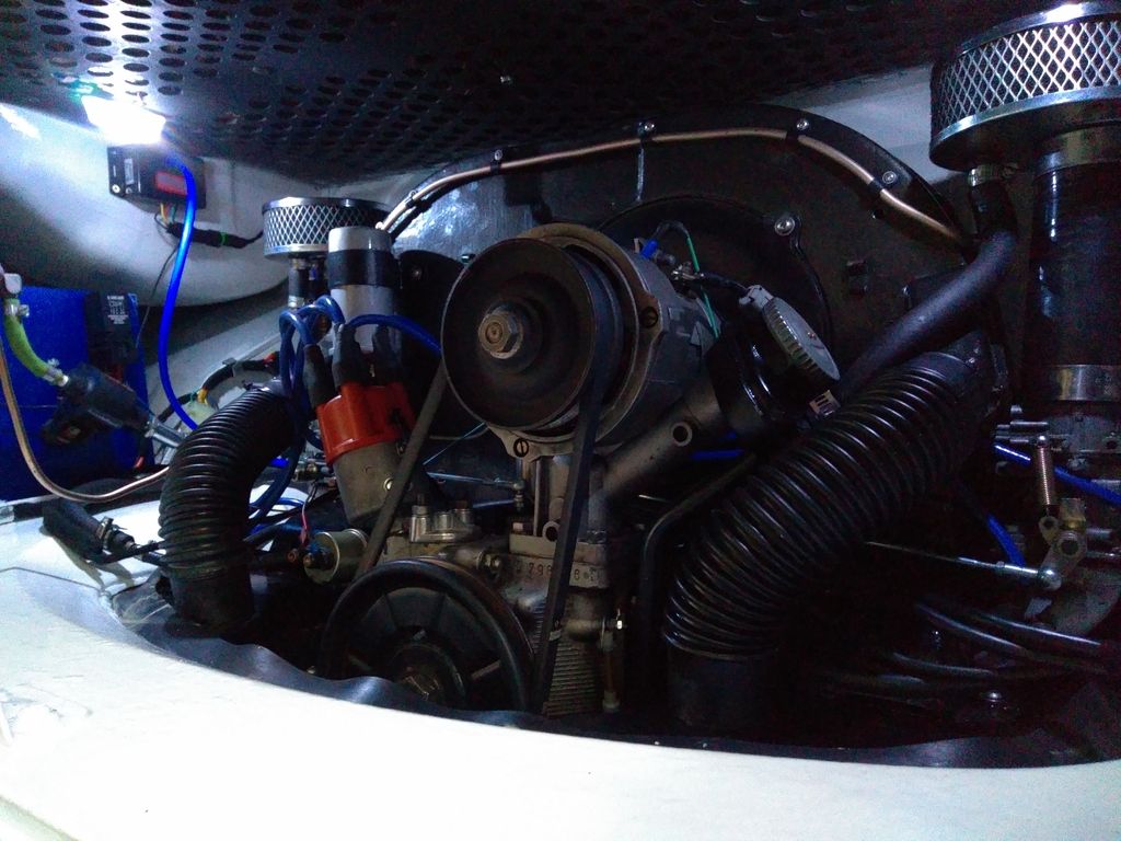
Picture 2 - Engine installed with Aldon Amethyst module


I will upload the timing curve I started with tommorow; along with the revisions made between then and now, with the reasonings behind each change. The basic/initial curve was derived from stock VW distributor curves, 4cyl Porsche distributor curves, some custom ignition maps from The Samba + ideal curve calculations.
 
Here we go with a bit more detail..

First off, heres a spreadsheet for calculating RPM at a chosen speed in a selected gear.
https://drive.google.com/open?id=0B9xT79c4E08gVURha0VHRFhpemc
Yellow cells are input cells; based on your gearbox specs, wheel size and speed of interest. The current values for 1st to 4th are CA code 002 values. The R&P value is based on a freeway flyer box or box with that modification done to it.
As mentioned previously, its not entirely relevant for this thread but may be useful to someone.

This spreadsheet creates a 3D Ignition curve based on the values per each 500rpm band & 2Hg vacuum bands in the Amethyst unit; again not particularly useful, but good for creating pretty pictures!
https://drive.google.com/open?id=0B9xT79c4E08gSmJOa2JyVEtVak0

I have also got a spreadsheet that details my current ignition curve, other dizzy curves etc. and an ideal curve based on calculation of flame burn time and such. However I cannot get access to this at the moment so will post that further into the thread.

Timing set up -
My distributor set at 7.5 degrees BTDC static timing, so all values in the below are + 7.5 degrees which can be seen in the 3D map creator spreadsheet above.

This was my initial map, ignoring the maximum advance value(incorrect on this version).


I uploaded this map to the unit, and drove the bus up and down the same road multiple times to tweak the curve by listening for detonation.
I found that adding 10 or so degrees throughout the range did not seem to make the engine detonate, which appeared wrong. So went back to this curve and took the bus on a longer run the following day.
On that longer run I could feel the engine felt underpowered and had some hesitation.

I thought it would be best to check the idle timing with a strobe at this point, which confirmed my concern that the static timing was actually incorrectly set. It was found to be almost 8 degrees too little, so close to firing at TDC. This explained why adding 10 degrees to the overall curve did not cause detonation.
So I set the timing correctly at 7.5 degrees BTDC at idle and ran it like that for a week or so, making very minimal changes to the timing curve based on driving feel and any detonation.
After tweaking the mechanical curve to get the most performance, I was left with the map below.

However some hesistation was still noticeable when accelerating, so I began to investigate and found the ported vacuum from one carb did not appear to bring in any vacuum advance on part throttle. I ordered a few bits to tee into the balance pipe so the MAP sensor in theAmethyst would be reading the actual MAP vacuum. After installing these parts, I tweaked the curve once more to suit the vacuum readings the MAP sensor gave in the software while the engine was running.

Note some additional advance at lower RPM's than the previous map, I found this seemed to be OK now I had some sorted the vacuum advance.
I took the bus for a reasonably long run with that advance layout, and I noticed there was very slight detonation over the RPM range, so took a couple of degrees out of the mechanical timing. Leaving me with this...


Which as far as I can tell, is the correct advance curve to produce the most power from my engine set up.
When this curve is compared against most of the stock dizzy curves, it is found that I have got significantly more timing at the lower range between about 1250-2500 rpm.This helps with off idle throttle response and torque low in the rev range.

I have also found that I seem to be getting random misfires from my engine which are significant enough to be felt at high speeds and cause idle RPM fluctuations; based on my current diagnosis this appears to be caused by the Amethyst module not triggering the spark every now and again.. Aldon have sent me a power conditioner to place in the power feed line to the Amethyst to try and rectify this issue, so I will continue to update this thread as I work through solving this issue.
 
Thanks Nobbly.
I've got a bit more to add yet, and will update some more as I go.

I've updated the thread title, should be a bit more representative of the content.
 
Right.... this is the spreadsheet I have put together to compare multiple advance curve layouts available on the internet and an ideal curve calculated based on the information on Volksbolts that has been used to calculate a type 4 ideal advance curve. The ideal advance curve reference is http://www.volksbolts.com/faq/combustion.htm . I have not validated the information on that page, and it may be incorrect but I have assumed volksbolts is a reasonably reliable source of information. The majority of the text within the spreadsheet is a copy of the volksbolts page, and not my own.

All distributor curves used are based on those available on the Ratwell site, http://www.ratwell.com/technical/IgnitionSystem.html , Posted by members on The Samba forum or Sparking Plugs for the Porsche curve http://www.sparkingplugs.com/8.html . Again I have not validated any of their data, but assume it to be correct.

https://drive.google.com/open?id=0B9xT79c4E08gYjY0R1VDR3RoU00

The method of ideal curve calculation should be reasonably easy to follow if you read the volksbolts page or the text within the spreadsheet.

It is clear from this spreadsheet that my final, or almost final(I'll get into that shortly) curve pulls in approx. 3-4 degrees or more additional advance between 1000-2500 rpm than the majority of the VW distributor curves. The 205P curve would appear to be one of the most aggressive distributor curves used on these engines, although the 205AB pulls in more advance at 1500rpm. These two curves with their highest values merged together are likely to represent almost the best curve for a bone stock engine, giving the best efficiency and power, along with the lowest exhaust gas temperatures.

The SVDA curve is almost the least aggressive in ramping up the timing, indicating a very conservative set up in these distributors. This conservative curve is ultimately lost efficiently and power, but I guess is 'one-fits-all' curve that is never going to cause detonation at low revs with pisswater fuel(I think that's a technical term?!). It is also likely to increase exhaust gas temperatures(EGT) due to the late burning of fuel at low revs, and high EGT temps are not good in these engines which already abuse the exhaust valves!

The Porsche curve is a somewhat middle ground, and is an exceptionally clean and smooth profile. The base advance on that distributor was only 5 degrees BTDC, hence the large gap between it and the other curves on the first graph. The second graph including the base advance is more representative. The only other thing to note from the Porsche curve is a significantly higher total advance at 34 degrees versus the VW curves that max at about 31 degrees, this could be due to the light weight nature of the 312 allowing additional advance at high RPM without detonating due to reduced engine load... or the Porsche tweaked engine in the 312 had a slightly different head/chamber layout that reduced flame speed. I have not compared the VW and Porsche engines in detail to provide much further detail there.


So, moving back to the issues I was having... I have installed the power conditioner(two capacitors and a diode, in a little box) into the power line to the Amethyst module and this appears to have solved the misfiring issue. This would lead me to believe there are some voltage spikes on the 12v input, I presume it is induced voltage from the HT leads or coil but could be related to the alternator. I did think about looking at the power input voltage in an oscilloscope but decided it was overkill given the conditioner appears to have rectified the issue.

Whilst installing the conditioner I also changed the 500rpm curve point from 0 degrees to 3 degrees. This was to help smooth the idle out a little, and help the engine pull the idle RPM back to normal if it drops significantly below for any reason; almost stalling etc.

Think this is all the data and info I can provide on this subject at the moment, but if anyone has any questions/comments please reply on this thread or PM me.


Sent from mTalk
 
Brilliant thread on how to take a stock engine with twin carbs to the next level. Seems like a handy little unit. I have the CB quick tune on my devon 2165 [@160HP] and love it.

i dont want this thread to get lost when your finished so will pin and move it to technical how-tos at a later date.
 
Johnny said:
Brilliant thread on how to take a stock engine with twin carbs to the next level. Seems like a handy little unit. I have the CB quick tune on my devon 2165 [@160HP] and love it.

i dont want this thread to get lost when your finished so will pin and move it to technical how-tos at a later date.
Thanks Johnny.

Ultimately I guess these things are just something else to tinker with, but the additional power and efficiency gains can be quite large as I'm sure you are aware!

Sent from my Wileyfox Swift 2 using Tapatalk


I love the quick tune as its a step up even from a modern car. it will analyze driving style and plot a curve and switching curves on the fly is great too. It was on a new engine but worth the investment.

I have a couple of stock engines which i'm looking to upgrade and will definitely look into this device as a low cost option.
 
Couple of months since the last update.

Having issues with random misfires again, so I'm currently in the process of taking scope outputs of the inputs and outputs of the Aldon box to determine the reason.
I'm discussing this in detail with Aldon's electronics engineer/consultancy who designed the box, Osney Consulting that is. They are keen to solve the problems but think they would be unable to replicate my issues on the test bench or one of their cars(which have been running well for years!), hence why I am looking at it with my scope.

Hopefully I'll have it solved and fixed in the coming weeks!

Sent from my Wileyfox Swift 2 using Tapatalk

 
So it's nearly 4 months since my last update to this thread.

I've been back and forth to Aldon&Osney Consulting for the best part of that, coming to what appears to be no resolution to my issue. I've had the amethyst upgraded to new firmware, taken countless scope traces, changed back to points to trigger the unit, along with many other potential fixes.
None have which have worked, it would appear I have unearthed an underlying issue with the amethyst, that is quite apparent on my set up but it would appear to be non-existent on every other Amethyst used on other cars.
The technical guys at Aldon and their consultant appear to be unable to determine the cause of my issues, and are as confused as myself.

Given this, I'm in the process of trying to return the product as it would appear unfit for my purpose.

Not sure what the alternatives are at the moment.

I still believe the Amethyst is an excellent product and great if it works correctly in your application; but if an issue occurs it is very difficult to identify; Aldon/Osney Consulting's customer service throughout has been excellent even though they have been unable to identify the problem.

Sent from my Swift 2 using Tapatalk
 

Latest posts

Top